866-685-4443 | Get in Touch Online ...
Heat Trace Cable Calculator
This tool takes the details of your heat tracing application and calculates the figures you'll need to install the cable, including: wattage losses to outside air, length of cable required, and the optimal spiral pitch for installation.
To get started, enter the following details. You can change any as needed to see updated results in real time.
| Pipe size | Pipe length | Minimum ambient temp. | Designed holding temp. | Insulation material |
|
NPS Actual O.D.: in. |
ft | °F | °F | |
| Difference must not exceed 400°F. | ||||
Wattage losses
Your expected wattage losses per foot of pipe (W/ft) are shown in this table.
| Insulation thickness → | 1" | 1.5" | 2" | 2.5" | 3" |
| Fiberglass | |||||
| Cellular glass | |||||
| Calcium silicate | |||||
| Polyurethane | |||||
| Polyurethane | — | — | — | — | — |
Click on a cell in the table above to choose a style and thickness of insulation, and the table below will show how much cable is required to offset heat losses with your chosen insulation.
| Self-limiting styles | Constant-wattage styles | Other constant- wattage style: enter rated W/ft |
||||||||||
| SLCAB (to 150°F) | SLMCAB (to 250°F) | |||||||||||
| Nominal W/ft | 3 |
5 |
8 |
10 |
5 |
10 |
15 |
4 |
8 |
12 |
18 |
|
| Expected W/ft at holding temp. |
4 | 8 | 12 | 18 | ||||||||
| Cable needed, ft (Excludes valves) |
— | — | — | — | — | — | — | — | — | — | — | — |
A length with a * denotes that the power delivered by the cable is more than enough to bring the pipe to your chosen setpoint. While a temperature controller is recommended for all heat tracing applications, in this case it should be considered essential.
Click on a cell in the bottom row of the table above to choose a style of cable. The illustration below will update to show recommended spiral pitch for installation.
Spiral pitch
Valves
Valves require special attention in heat tracing applications because their greater surface area causes them to lose heat faster than pipe, making them more vulnerable to freezing. It's recommended to use extra cable on any valves, in order to counteract this. Use the table below to get recommendations on how much extra to use.
Note that the illustration above shows only one way to add extra cable around valves. For valves that require large amounts of extra cable, a zigzag wrapping pattern is more appropriate. Only self-limiting cable can safely cross over itself.
| Component illustration | Valve/component Click/hover for visual |
Quantity | Add'l cable, each (ft) |
Add'l cable, total (ft) |
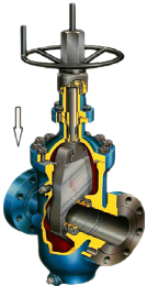
Gate valve
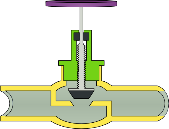
Globe valve
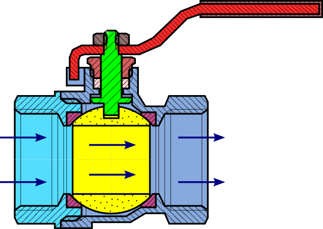
Ball valve
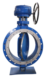
Butterfly valve
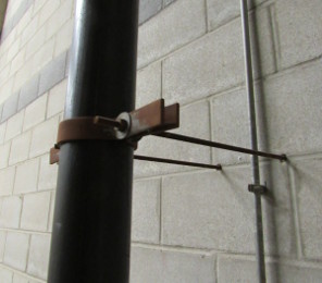
Pipe support
|
Gate valve | |||
| Globe valve | ||||
| Ball valve | ||||
| Butterfly valve | ||||
| Pipe support | ||||
| Total: | ||||
| Plus rest of cable: | ||||
Please note:
- Liquid flowing through a pipe greatly increases heat loss, and this calculator does not yet support calculations for flowing liquids.
- The figures shown are for applications where a temperature is being maintained; this calculator does not show calculations for raising a pipe to a specific temperature.
